Sensors
The Vehicle-Infrastructure platform is shown in Fig. 1. Our onboard sensor suite consists of a multi-camera setup (event camera, industrial camera,
and infrared camera) equipped with three LiDARs, onboard IMU, two GNSS receivers, and GNSS-RTK/INS systems.
The specific specifications of each sensor are presented in Table. 1. .
An Intel NUC (i7-1260P, 32GB RAM) and an industrial computer (i7-10610U, 32GB RAM) are used to run sensor drivers, and record data into ROS bags on the Ubuntu system.
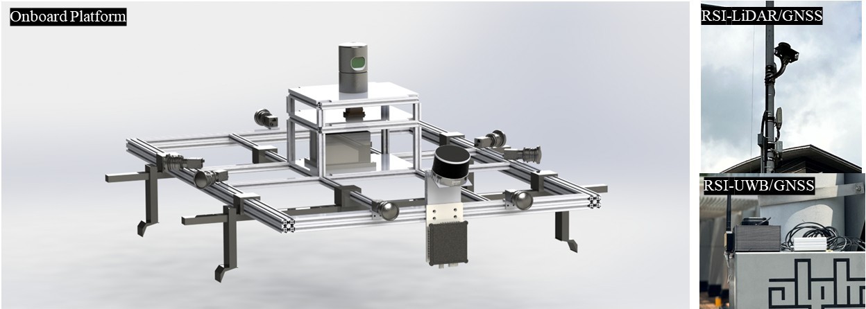
Vehicle-Infrastructure sensor platform
The details of full sensors setup can be found below:
| Platform | Sensor Type | Description |
|---|---|---|
| Onboard Platform | Hikvision MV-CS050-10GC PRO × 7 |
|
| Hesai XT-32 |
|
|
| Velodyne VLP-32E |
|
|
| GPAL-Ares-R7861 Radar |
|
|
| Xsens MTi-30 IMU |
|
|
| U-Blox ZED-F9P |
|
|
| NovAtel SPAN-CPT |
|
|
| Roadside Infrastructure | Innovusion Jaguar LiDAR |
|
| U-Blox ZED-F9P |
|
|
| UWB Nooploop |
|
We use an Ethernet topology for data transmission and time synchronization, as shown in Fig. 2.
All independent devices and the PTP server are synchronized using NMEA and PPS signals from a u-blox M8T GNSS receiver.
PTP server synchronizes devices clocks by broadcasting PTPv2 messages. Ethernet cameras are triggered via GigE Vision with a timing accuracy of < 0.005s.

Visual sensors
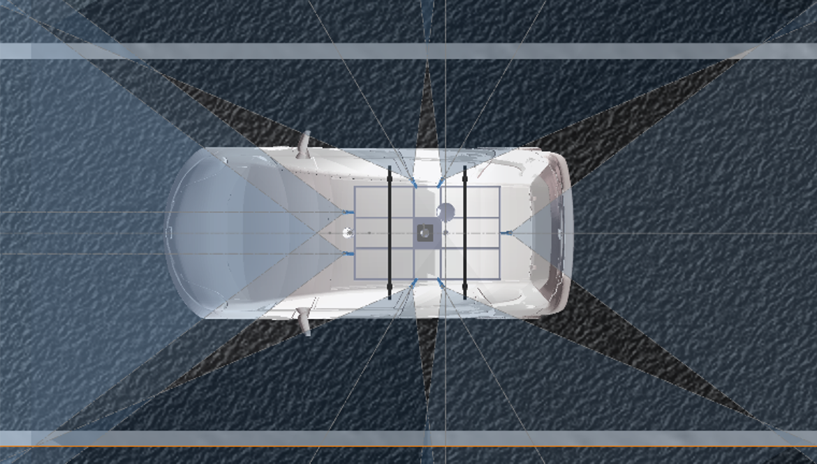
Seven Hikvision MV-CS050-10GC PRO cameras with 4mm lenses capture 2200×1740 RGB images at 10 Hz.
Two are forward-facing stereo cameras, while five form a 360° surround setup with 60° spacing and 20° overlap. The FOV coverage is shown in Fig. 3
Image synchronized trigger is achieved via the GigE Vision protocol.
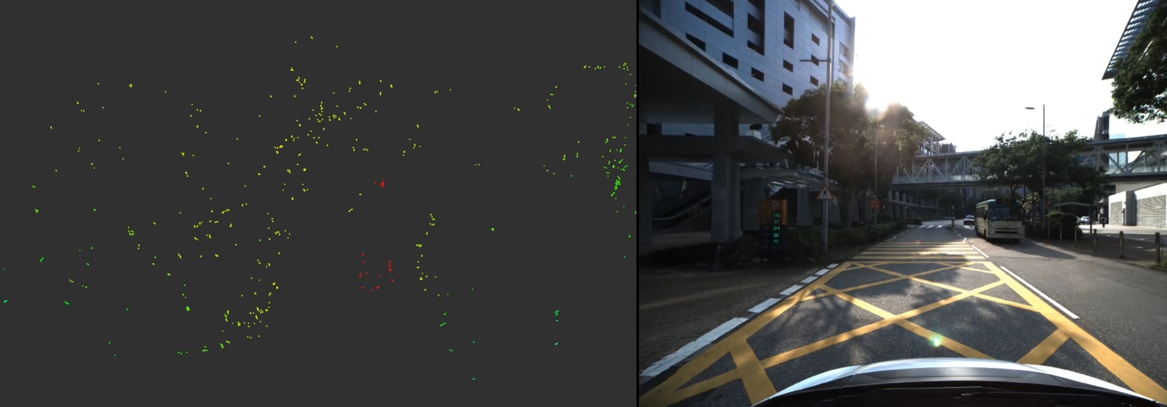
4D Radar
A front-mounted 4D radar GPAL Ares-R7861 measures object position, velocity, and distance in real time, producing 3D point clouds with velocity data.
It offers a 150° horizontal FOV and operates at 13 Hz. The point cloud view can be found in Fig. 4
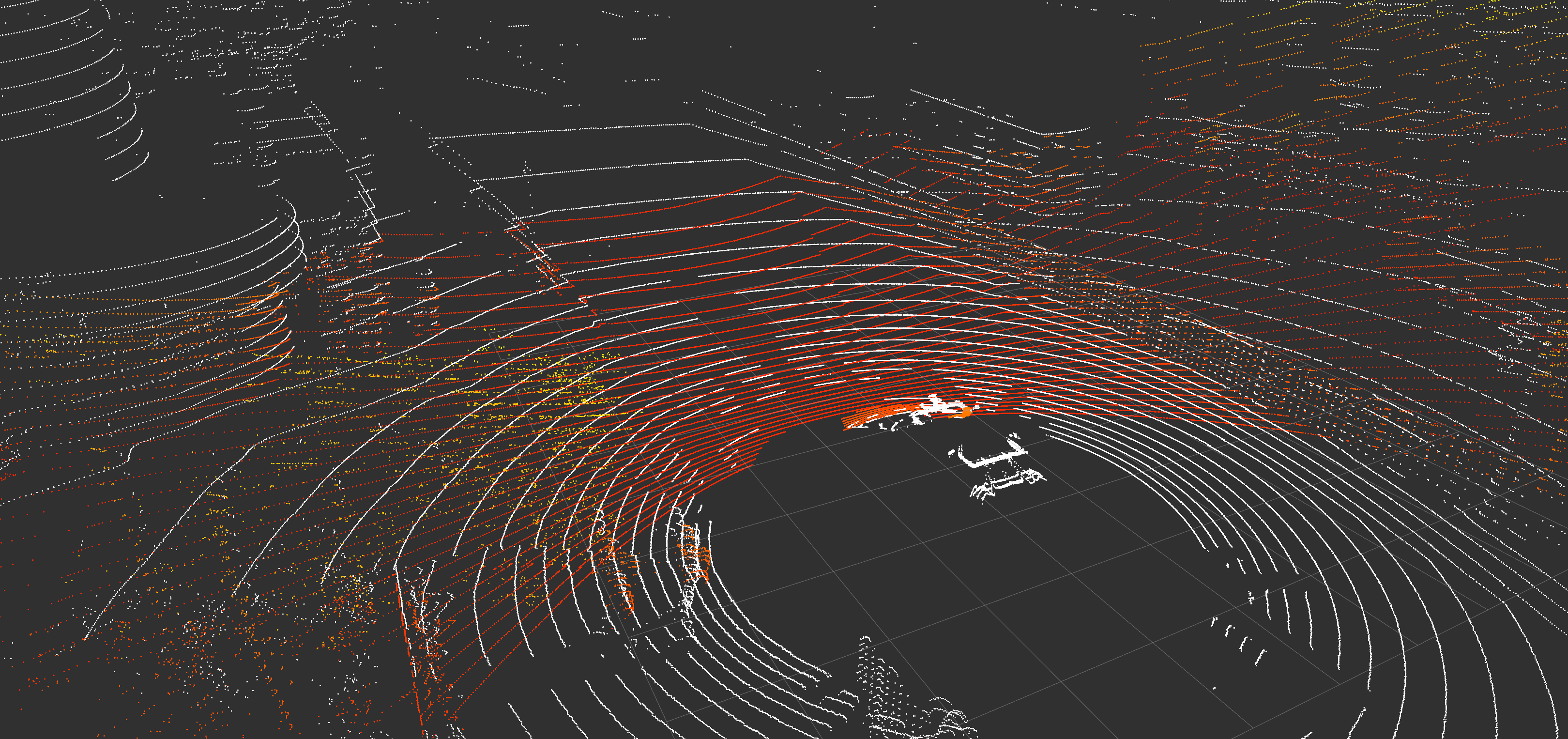
Mechanical LiDAR
Two mechanical LiDARs are used: a Velodyne HDL-32E on the vehicle roof for horizontal surroundings and a slanted Hesai XT-32 at the front for detailed urban architecture.
Two LiDAR point clouds are fused as Fig. 5. Both operate at 10 Hz.
Roadside LiDAR
Innovusion Jaguar LiDAR at 300 Lines cover the roundabout areas
Roadside UWB
We deployed 4 UWB anchors with RSI, which ensure the communication between vehicle and RSU at the roundabout area.